Scaling Bandwidth for Stretched Segments in an NSX Federation Environment
I recently got involved with a customer who had deployed NSX Federation between two locations, mostly for the use case of providing the same L2 networks on both locations, in other words ‘Global’ or Stretched Segments . They were witnessing performance issues and narrowed it down tot the fact that the NSX Edge Nodes were running out of capacity. Scaling up the bandwidth between locations by scaling out the NSX Edge Cluster to accommodate hundreds of Stretched Segments is totally achievable and can be capacity planned accordingly, but information how to do that is a little scattered across documentation and blog sites, so I decided to write this little blog about it.
An NSX Segment in a non-federated NSX Instance will use a given GENEVE Virtual Network Identifier (VNI). All Tunnel End Points (TEPs) are able to communicate with one another across the underlying Switch Fabric and the NSX Control Plane has connections to all NSX Transport Nodes hosting these TEPs (on ESXi Hosts and NSX Edges) to establish said segment.
However, in an NSX Federated Environment with two locations, several GENEVE VNI will be stitched together to form a single Stretched Segment:
a VNI for Location / NSX Instance 1
a VNI for Location / NSX Instance 2
a VNI between the Locations, which uses TEPs on NSX Edge Nodes, called Remote TEPs (RTEP).
These RTEPs have their own configuration attributes like VLAN id and IP Addressing information, just like regular TEPs. In NSX 4.2.1 and older releases NSX Edge Nodes only support a single RTEP, and although two NSX Edge Nodes in an NSX Edge Cluster can form an ‘RTEP-group’ for High Availability, only Active/Standby is supported across the RTEP Group. Furthermore only the ‘non-preempt’ High Availability mode is supported for RTEPs, in other words, if one of the NSX Edge Nodes in an RTEP Group should fail, all RTEP communication fails over to the second NSX Edge Node, but upon an eventual recovery of the initial NSX Edge Node, its RTEP would not go back to active mode, but would remain Standby for all the Stretched Segments that were established across the RTEP Group.
NSX Stretched Segments always have the same ‘stretch’ as the NSX Gateway they connect to, and this is the same for Stretched Tier-0 Gateways, Stretched Tier-1 Gateways, as well as Stretched Tier-1 Gateways that only have Distributed Routing (Tier1-DR_Only) configured, which in turn inherit the same stretch as the Stretched Tier-0 Gateway they are connected to. Although Tier-1-DR_Only Gateways do not rely on NSX Edge Nodes, as the DR component resides in the hypervisors in the ESXi hosts in all Locations it is stretched to, the Segments connected to it DO rely on NSX Edge Nodes, in order to establish the RTEP functionality as outlined above. In other words, ALL NSX Stretched Segments that are connected to the same Tier-1 Gateway, will leverage the same RTEP Group on a pair of NSX Edge Nodes, with only one NSX Edge Node Actively forwarding traffic.
This is important for capacity planning purposes, and care should be taken that the combined traffic across Stretched NSX Segments that are attached to the same Tier-1 Gateway, does not exceed a single NSX Edge Node capacity. Although Stretched NSX Segments are initially load-shared across two NSX Edge Nodes in an RTEP Group, one should always assume for capacity plan purposes that one NSX Edge in the RTEP Group is Standby for all the Stretched Segments it is serving, as only non-preempt Active/Standby is supported for RTEP Groups.
RTEP-Groups are distributed across all NSX Edge Nodes in an NSX Edge Cluster on a ‘least-allocated’ basis. The NSX Manager chooses two NSX Edge Nodes which has the least amount of “used” RTEPs, regardless of Active/Standby Status, and allocates the RTEP-Group to them. Ofcourse this assumes more than two NSX Edge Nodes are configured in the NSX Edge Cluster. Optionally one can choose to configure ‘Failure Domains’ on the NSX Edge Nodes, in order to make sure that the Active and Standby RTEPs reside in different Availability Zones. Although the documentation only refers to the use of Failure Domains for NSX Gateways with Service Routing (SR) components, it equally applies to RTEP Groups used with NSX Stretched Segments attached the Tier-1-DR_Only Gateways.
In case a pair of NSX Edge Nodes are running out of capacity because of the RTEP related cross-location traffic (again assume the worst case where all RTEPs are active on a single NSX Edge Node), one should:
Deploy another pair of NSX Edge Nodes, configure the RTEPs on them, and add them to the same NSX Edge Cluster as the initial pair of NSX Edge Nodes, and this in both locations. Optionally configure the Failure Domain on the NSX Edge Nodes.
Deploy another Tier-1 Gateway (For example DR_Only ) and connect new Stretched NSX Segments to it, and/or move existing Stretched NSX Segments to it.
I decided to verify this procedure and came across some head-scratching moments, so I decided to incorporate my findings in this blog.
The lab I used had NSX Federation already configured across 2 Locations, and 3 NSX Segments already stretched, attached to two Stretched Tier-1 Gateways, across an NSX Edge Cluster with two NSX Edge Nodes in each location:
NSX Segment xregion-seg01, connected to the Active/Standby Tier-1 Gateway Çross-Tier-1
NSX Segments web-seg, and db-seg, both connected to the DR_Only Tier-1 Gateway T1-VI-2Tier.
Both Tier-1 gateways were connected to the Stretched Tier-0 Gateway 'Global-Tier-0’.
You can verify where the NSX Management Plane decided to Put the Active and Standby RTEPS for those segments by clicking on ‘VIEW STATISTICS’ on the expanded Segments configuration, and then clicking on ‘STATUS’, as can be seen on the next screenshots taken from my lab:


Alternatively, you can use the CLI, by executing ‘get logical-switch <uuid> l2forwarders high-availabity state’ for the Segment with the given UUID, as shown below:
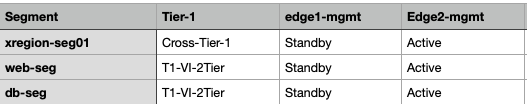
Obviously, as I only had two NSX Edge Nodes, all Segments were leveraging that pair. I also previously put one NSX Edge in maintenance mode, and took it out of maintenance mode again, so that all RTEPs were active on NSX Edge ‘edge2-mgmt’. I thus need up with the following state across both NSX Edge Nodes:
I then created two new NSX Edge Nodes, 'edge3-mgmt' and 'edge4-mgmt', but noticed I could only add them to the existing cluster if they had their RTEPs configured. The 'Configure Remote Tunnel End Point’ wizard under the Quick Start menu in the system tab wasn’t much use here, as it only allows one to configure RTEPs for a new NSX Edge Cluster, not if you want to add NSX Edge Nodes to an existing NSX Edge Cluster. The way to do this is by navigating to the NSX edge in question in System/Fabric/Nodes , clicking on the NSX edge and then selecting ‘Tunnels’, as shown below:
I could then configure the RTEP VLAN, IP Address Method, which was leveraging an already created IP Pool. Note that one might have to add more IP Address Blocks to this IP Pool , under the Networking tab, and navigating to IP Address Pools.
After configuring this for both NSX Edge Nodes, I was able to add them to the existing NSX Edge Cluster, ending up with 4 NSX Edge Nodes in the NSX Edge Cluster. I then deployed a new Tier-1 DR_Only, attached it to the existing Stretched Tier-0, and attached a new segment to it, after which I checked which NSX Edge Nodes were chosen as Active and Standby for the RTEP Group across the NSX Edge Cluster. I repeated this four times, ending up with 4 additional DR__Only Tier-1 Gateways, each with one segment attached. The next 4 screenshots shows which NSX Edge Nodes were chosen.


In summary, the first three RTEP groups ended up on edge3-mgmt and edge4-mgmt, as they had the least amount of allocations. the fourth one ended up a tie, and the algorithm choose edge1-mgmt and edge4-mgmt as the RTEP group pair. The following table summarises the result, which clearly shows the way the algorithm works:

Additional detailed information on all things NSX Federation can be found in the NSX Multi-Location Design Guide written by the amazing Dimitri Desmidt, which can be found here. I hope this blog clarified how Stretched NSX Segment to NSX Edge Node allocation works, and it helps you to capacity plan your NSX Edge Cluster for your NSX Federation deployment!